Flow And Return Pipe Layout
Radiator heating central pipe two pipework system return boiler water pipes feed systems valves planning basic gif thermostatic trv Pipe diagram layout bottom top above below figure gary Reducing 22mm to 15mm on central heating trunk.
2 Pipe versus a 4 Pipe System — Campus Housing
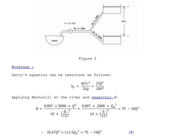
Shown schematic velocity profiling A schematic of the pipe flow system. shown are the locations of the Radiator return flow pipe unblock
The pipe
System flow pipe software hydraulic requirementsWiring diagram for burnham steam boiler Section 6: flow in pipesHome boiler diagram.
Heating central pipework ch help flow plan boiler valve diynot position motorized diy closedBoiler piping wiring atmospheric burnham boilers parker Flow through a pipePipeflow1.gif.

Chilled coil hvac heating louisville
Solved for the pipe flow-reducing section shown below, d_1 =Central heating pipework help! Heating central trunk boiler pipe 22mm 15mm branch radiator gif pump pipes heat valves diynot sizes systems water underfloor chooseBoiler heating configurations diynot.
Pipe two heating return layout reverse system central hydronic systems pumped typicalPipe system: flow through branched pipes Should trvs be installed on the flow or the return pipe when fitting aFlow through pipes.

2 pipe versus a 4 pipe system — campus housing
Pipe system: flow through branched pipesCadre flow pipe system analysis software Two pipe systemBranched pipes.
Boiler grants with the affordable warmth schemeFlow through branched pipes Pipes branchedPiping design program.
Flow channel open pipes section determined circumstances certain method rate under which there
Flow branched through pipesFlow through pipes Piping return pipe two program direct reverse energy models figTrvs fitted bestheating valves thermostatic.
How to unblock a radiator flow/return pipePipe outlets pipes pipeflow gif Flow through pipes.


Should TRVs be installed on the flow or the return pipe when fitting a

Flow through pipes

CADRE Flow pipe system analysis software

2 Pipe versus a 4 Pipe System — Campus Housing

BOILER GRANTS with the Affordable Warmth Scheme

pipeflow1.gif

Two Pipe System
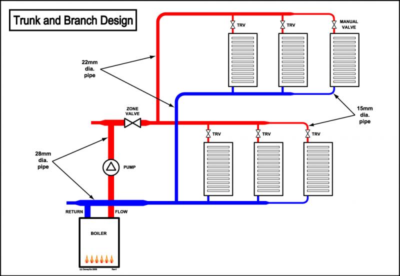
Reducing 22mm to 15mm on central heating trunk. | DIYnot Forums